1. Introduksjon
This manual provides essential information for the safe installation, operation, and maintenance of the Pilz PNOZ X3P Safety Relay, model 777314. The PNOZ X3P is designed for monitoring E-STOP pushbuttons, safety gates, and light grids in industrial applications, ensuring personnel and machine safety.
2. Sikkerhetsinstruksjoner
ADVARSEL: Failure to follow these safety instructions can result in serious injury or death, and damage to equipment.
- Only qualified personnel familiar with industrial safety standards and electrical systems should install, operate, or maintain this device.
- Disconnect all power before performing any installation, wiring, or maintenance tasks.
- Sørg for at all kabling er i samsvar med lokale og nasjonale elektriske forskrifter.
- Do not bypass or disable safety functions.
- Regularly inspect the device and associated safety components for damage or malfunction.
- Use only genuine PILZ replacement parts.
3. Produktet er overview
The Pilz PNOZ X3P (Model 777314) is a safety relay designed for monitoring safety functions. It features:
- Funksjon: E-STOP, safety gate, light grid monitoring.
- Kontaktkonfigurasjon: 3 Normally Open (NO) safety contacts, 1 Normally Closed (NC) auxiliary contact, 1 Semiconductor Output (SO).
- Forsyning Voltage Område: 24-240VAC/DC (Coil Voltage: 24V AC/DC).
- Driftsmodus: Automatisk tilbakestilling.
- Bredde: 45 mm.
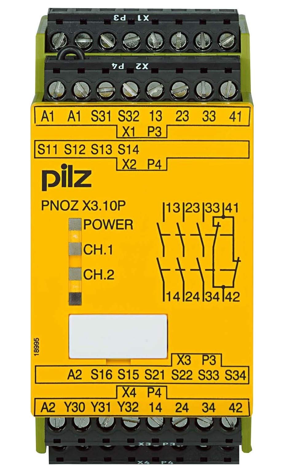
Figur 1: Foran view of the Pilz PNOZ X3P Safety Relay, showing terminals and indicators.
4. Oppsett og installasjon
4.1 Montering
Mount the PNOZ X3P on a 35mm DIN rail in a control cabinet. Ensure adequate ventilation around the device to prevent overheating. Maintain proper clearance from heat-generating components.
4.2 Elektriske tilkoblinger
Before making any electrical connections, ensure the main power supply is disconnected and locked out. Refer to the wiring diagrams for correct terminal assignments.
5. Kabling
The PNOZ X3P supports 1-channel or 2-channel wiring for safety inputs. The choice depends on the required safety integrity level (SIL) and performance level (PL).
5.1 Input Wiring (E-STOP, Safety Gate, Light Grid)
- 1-Channel Wiring: Connect the safety device (e.g., E-STOP) to a single input channel. This configuration offers basic safety.
- 2-Channel Wiring: Connect the safety device to two independent input channels. This configuration provides redundancy and higher fault tolerance, suitable for higher safety requirements.
5.2 Output Wiring
The relay provides 3 NO safety contacts for controlling power to hazardous machinery and 1 NC auxiliary contact for signaling purposes. The 1 SO (semiconductor output) can be used for diagnostic feedback to a PLC.
Ensure that the load connected to the safety contacts does not exceed the maximum switching current of 15 Amps and maximum switching voltage på 240 volt.
Figur 2: Eksample wiring diagram for a 2-channel E-STOP application. (Actual diagram not provided, refer to product documentation for specific wiring.)
6. Bruksanvisning
The PNOZ X3P operates in an automatic reset mode. Once the safety input circuit is closed (e.g., E-STOP released, safety gate closed), the safety relay will automatically energize its output contacts, provided no faults are detected.
6.1 Oppstart
Upon applying power, the relay performs an internal self-test. If the safety inputs are closed and no faults are present, the output contacts will close, and the status indicators will illuminate.
6.2 Safety Function Activation
When a safety input is opened (e.g., E-STOP pressed, safety gate opened), the PNOZ X3P immediately de-energizes its safety output contacts, bringing the monitored machine to a safe state.
6.3 Tilbakestilling
Due to its automatic reset function, the relay will re-energize its outputs as soon as the safety input circuit is restored and no faults are present. Ensure that the machine can only restart safely after a reset.
7. Vedlikehold
Regular maintenance is crucial to ensure the continued safe operation of the PNOZ X3P safety relay.
- Periodisk inspeksjon: Visually inspect the device and its wiring for any signs of damage, loose connections, or contamination.
- Funksjonstest: Periodically test the entire safety circuit, including the PNOZ X3P, by activating the connected safety devices (E-STOP, safety gate, light grid) to verify their proper function.
- Rengjøring: Keep the device free from dust and debris. Use a dry, soft cloth for cleaning. Do not use abrasive cleaners or solvents.
8. Feilsøking
If the safety relay does not function as expected, consider the following common issues:
| Problem | Mulig årsak | Løsning |
|---|---|---|
| Outputs do not energize after power-up. |
|
|
| Outputs de-energize unexpectedly. |
|
|
If troubleshooting steps do not resolve the issue, contact PILZ technical support.
9. Tekniske spesifikasjoner
| Parameter | Verdi |
|---|---|
| Modell | 777314 |
| Merke | PILZ |
| Driftsmodus | Automatisk |
| Spole voltage | 24 volt (AC/DC) |
| Kontakt gjeldende vurdering | 6 Amps |
| Maksimal koblingsstrøm | 15 Amps |
| Maksimal svitsjvoltage | 240 volt |
| Varevekt | 0.64 pund |
10. Garanti og støtte
PILZ products are manufactured to high-quality standards and come with a manufacturer's warranty. For specific warranty terms and conditions, please refer to the official PILZ webnettstedet eller kontakt din lokale distributør.
For technical assistance, product support, or to report a malfunction, please contact PILZ customer service. Have your product model (777314) and serial number ready when contacting support.
PILZ Official Webnettsted: www.pilz.com