1. Introduksjon
The DIYmall L298N Motor Drive Controller Board is designed for controlling DC motors and stepper motors. Built around the L298 dual full-bridge driver, this module provides robust performance for various applications, including robotics, smart cars, and other DIY projects. It features two independent channels, allowing it to drive two DC motors or one 2-phase/4-phase stepper motor.
2. Nøkkelfunksjoner
- Main Chip: Utilizes the L298N dual full-bridge driver.
- Termisk ytelse: Designed for low heat generation with outstanding anti-interference capabilities.
- Strømhåndtering: Supports a wide working voltage opptil 46V.
- Nåværende kapasitet: Capable of handling a large peak current of 3A and a continuous current of 2A, with a maximum power output of 25W.
- Motorkompatibilitet: Can drive one 2-phase stepper motor, one 4-phase stepper motor, or two DC motors.
- Integrated Regulator: Includes a built-in 78M05 5V regulator. When the drive power exceeds 12V, an external 5V power supply should be used for logic.
- Forbedret stabilitet: Equipped with a large capacity filter capacitance and afterflow protection diode for stable and reliable operation.
3. Oppsett og installasjon
Before connecting the L298N module, ensure all power sources are disconnected. Proper wiring is crucial for safe and effective operation. Refer to the wiring diagrams below for detailed connection instructions.
3.1 Strømforsyningstilkobling
- Connect your motor power supply (e.g., 12V) to the '+12V Power' terminal.
- Connect the ground of your power supply to the 'Power GND' terminal.
- If your motor power supply is 12V or less, the onboard 78M05 regulator can provide 5V for the logic circuit. In this case, ensure the 5V jumper is in place.
- If your motor power supply exceeds 12V (up to 46V), remove the 5V jumper and provide an external 5V power supply to the '+5V Power' terminal for the logic circuit.
3.2 Motortilkobling
- For DC motors: Connect the two terminals of the first DC motor to 'OUT1' and 'OUT2'. Connect the second DC motor to 'OUT3' and 'OUT4'.
- For stepper motors: Connect the four wires of a 2-phase or 4-phase stepper motor to 'OUT1', 'OUT2', 'OUT3', and 'OUT4' as per the stepper motor's wiring diagram.
3.3 Tilkobling av kontrollsignal
- Connect your microcontroller's digital output pins to 'Input1', 'Input2', 'Input3', and 'Input4' to control the direction of the motors.
- Connect 'Enable A' to a digital output pin (or PWM pin for speed control) on your microcontroller to enable/disable Motor A (OUT1/OUT2).
- Connect 'Enable B' to a digital output pin (or PWM pin for speed control) on your microcontroller to enable/disable Motor B (OUT3/OUT4).

Figure 1: L298N Motor Driver Board with labeled input/output terminals and the 5V jumper.
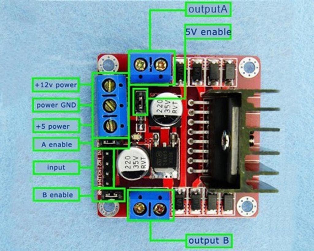
Figure 2: Detailed pinout diagram for the L298N module.
4. Bruksanvisning
The L298N module controls motors by manipulating the logic states of its input pins (Input1-4) and enable pins (Enable A/B). By setting these pins HIGH or LOW, you can control motor direction and speed (using PWM on enable pins).
4.1 DC Motor Control
For each DC motor, two input pins (e.g., Input1 and Input2 for Motor A) determine its direction. The corresponding enable pin (Enable A) controls its power and speed.
| Enable A | Inngang 1 | Inngang 2 | Motor A Action |
|---|---|---|---|
| LAV | X | X | Motor A OFF |
| HØY | HØY | LAV | Motor A Forward |
| HØY | LAV | HØY | Motor A Reverse |
| HØY | HØY | HØY | Motor A Brake (Fast Decay) |
| HØY | LAV | LAV | Motor A Brake (Slow Decay) |
Note: 'X' denotes any state (HIGH or LOW). For speed control, apply a Pulse Width Modulation (PWM) signal to the Enable A/B pins instead of a constant HIGH.
4.2 Steppermotorstyring
Controlling a stepper motor requires a sequence of HIGH/LOW signals across Input1-4 to energize the coils in a specific order. This sequence determines the direction and step angle of the motor. Both Enable A and Enable B pins should be HIGH for the stepper motor to operate.

Figur 3: Eksample wiring diagram for connecting the L298N to an Arduino and a stepper motor.
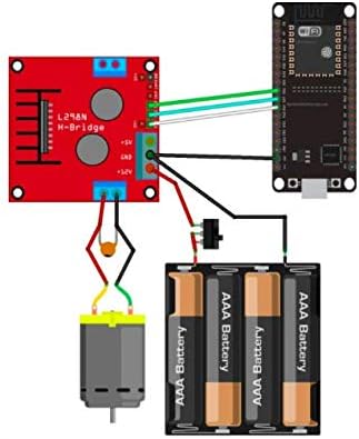
Figur 4: Eksample wiring diagram for connecting the L298N to an ESP32 and a DC motor.
Video 1: En overview of the L298N Motor Drive Controller Board, demonstrating its physical appearance and key components.
5. Spesifikasjoner
| Spesifikasjon | Verdi |
|---|---|
| Merke | DIYmall |
| Modellnavn | FZ0407 |
| Main Chip | L298N |
| Drivertype | Dobbel H-bro |
| Driftsvoltage (motor) | Opp til 46V |
| Toppstrøm | 3A |
| Kontinuerlig strøm | 2A |
| Maks kraft | 25W |
| Logic Voltage | 5V (via onboard 78M05 or external) |
| Dimensjoner | 1.6 x 1.6 x 0.8 tommer (ca. 40.6 x 40.6 x 20.3 mm) |
| Vekt | 9.07 g |
| Spesifikke bruksområder | Robotics, Automation, DIY Projects |
6. Vedlikehold
The L298N Motor Drive Controller Board is a robust electronic component designed for durability. To ensure its longevity and optimal performance, consider the following maintenance guidelines:
- Hold rent: Regularly inspect the board for dust or debris. Use a soft, dry brush or compressed air to gently clean the surface. Avoid using liquids.
- Miljøforhold: Operate and store the module in a dry environment, away from excessive moisture, extreme temperatures, and corrosive substances.
- Tilkoblingsintegritet: Periodically check all wire connections to ensure they are secure and free from corrosion or damage. Loose connections can lead to intermittent operation or component failure.
- Varmehåndtering: Ensure adequate airflow around the heatsink, especially during high-current applications, to prevent overheating of the L298N chip.
7. Feilsøking
If you encounter issues with your L298N Motor Drive Controller Board, follow these troubleshooting steps:
- No Motor Movement:
- Verify all power connections (motor power and logic 5V) are correct and supplying the appropriate voltage.
- Check if the 5V jumper is correctly placed or removed based on your motor power supply voltage.
- Ensure the Enable A/B pins are set to HIGH (or receiving a PWM signal).
- Confirm that the input pins (Input1-4) are receiving the correct logic signals from your microcontroller.
- Test the motors directly to ensure they are functional.
- Feil motorretning:
- Review your code or control logic to ensure the input pins are being toggled in the desired sequence for direction control.
- For DC motors, try swapping the OUT1/OUT2 or OUT3/OUT4 connections.
- Motor Runs Slowly or Weakly:
- Check the motor power supply voltage and current capacity. Insufficient power can lead to poor performance.
- If using PWM for speed control, ensure the duty cycle is set correctly.
- Verify that the motor's current draw does not exceed the L298N's continuous current rating (2A per channel).
- Overoppheting av modul:
- Ensure the heatsink is properly attached and has adequate ventilation.
- Reduce the load on the motors or decrease the operating voltage hvis mulig.
- Confirm that the motor current does not exceed the module's specifications.
- Intermitterende operasjon:
- Inspect all wiring for loose connections or cold solder joints.
- Check for electromagnetic interference (EMI) if operating near other electronic devices. Proper shielding or component placement may be necessary.
8. Garanti og støtte
For warranty information, technical support, or further assistance, please contact the seller or manufacturer directly. Retain your proof of purchase for any warranty claims.