Introduksjon
This manual provides essential information for the safe and efficient operation, installation, and maintenance of the Allen-Bradley PowerFlex 70 Variable Frequency Drive (VFD), model 20AC015A0AYNANNN. Please read this manual thoroughly before attempting to install, operate, or service the drive. Retain this manual for future reference.
The PowerFlex 70 VFD is designed to control the speed and torque of AC induction motors, offering precise control and energy efficiency in various industrial applications. This specific model is rated for 7.5 kW at 400V.
Sikkerhetsinformasjon
ADVARSEL: Dette utstyret inneholder høy voltage. Only qualified personnel should install, operate, or maintain this device. Failure to observe safety precautions can result in severe injury or death.
- Always disconnect power before working on the drive or motor.
- Wait for capacitors to discharge completely before touching any components.
- Sørg for riktig jording av drivenheten og motoren.
- Følg alle lokale og nasjonale elektriske forskrifter.
- Do not operate the drive with covers removed.
Oppsett og installasjon
Proper installation is crucial for the reliable operation of the PowerFlex 70 VFD. Refer to the detailed wiring diagrams provided with the product for specific connections.
Montering
Mount the drive vertically on a flat, stable surface. Ensure adequate clearance for cooling airflow. Avoid mounting in direct sunlight or areas with excessive vibration, dust, or corrosive gases.

Figur 1: Foran til høyre view of the Allen-Bradley PowerFlex 70 VFD, showing the main casing and ventilation grilles.
Kabling
- Strøminngang: Connect the incoming AC power to the L1, L2, L3 terminals. Ensure the voltage matches the drive's rating (400V).
- Motorutgang: Connect the motor leads to the T1, T2, T3 terminals.
- Jording: Connect the protective earth ground to the designated ground terminal.
- Kontrollkabling: Connect control signals (e.g., start/stop, speed reference) to the appropriate control terminals. Refer to the wiring diagram for specific terminal assignments.
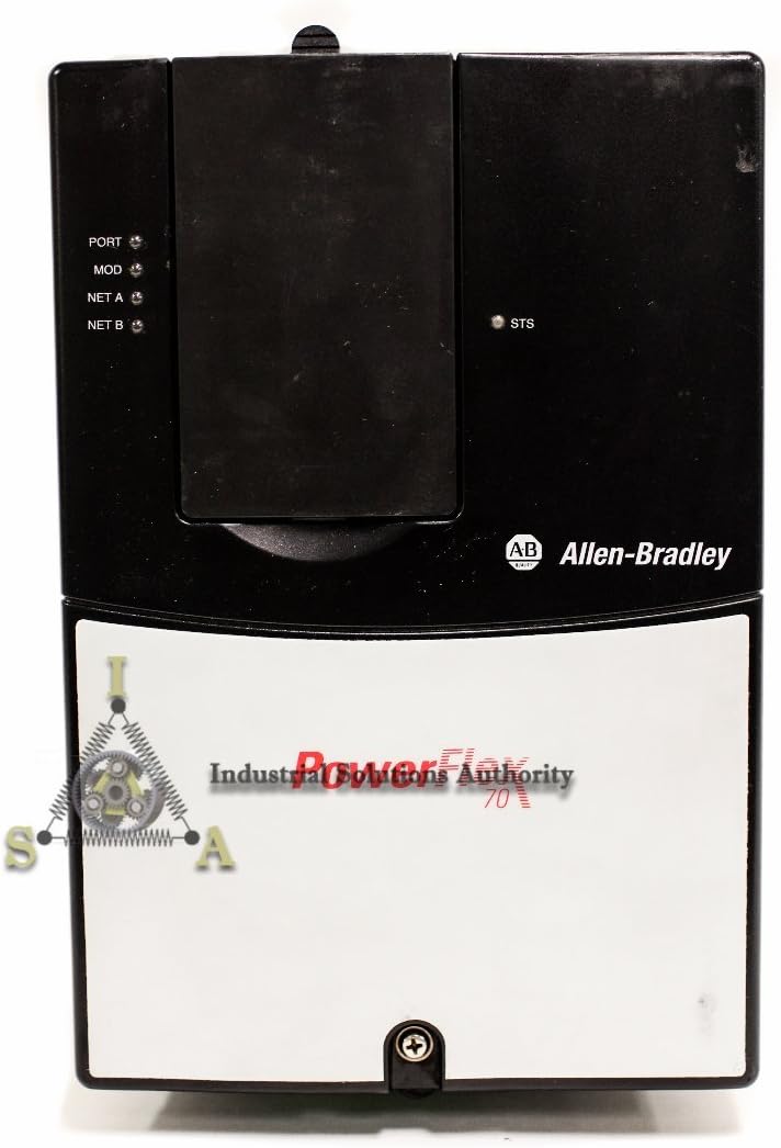
Figur 2: Foran view of the PowerFlex 70 VFD, highlighting the control panel area with status indicators (PORT, MOD, NET A, NET B, STS).
Bruksanvisning
After successful installation and wiring, the drive is ready for initial power-up and configuration.
Første gangs oppstart
- Kontroller at alle ledningstilkoblinger er sikre og korrekte.
- Apply main power to the VFD.
- Observe the drive's display and status indicators. The drive should power on and display a ready state or a default parameter.
Parameterkonfigurasjon
The PowerFlex 70 VFD requires configuration of various parameters to match the motor and application requirements. Common parameters include:
- Motor Nameplate Data (Voltage, Current, Frequency, RPM, Power)
- Acceleration/Deceleration Times
- Minimum/Maximum Frequencies
- Control Mode (V/Hz, Sensorless Vector, etc.)
- Input/Output Terminal Assignments
Refer to the comprehensive programming manual for a complete list of parameters and their functions. Parameters can typically be set via the drive's keypad or through communication software.
Starte og stoppe motoren
- Start: Initiate a run command via the keypad, digital input, or communication network.
- Hastighetskontroll: Adjust the motor speed using the speed reference input (e.g., analog input, potentiometer, or network command).
- Stopp: Issue a stop command via the keypad, digital input, or communication network. The drive will decelerate the motor according to the programmed deceleration time.
Vedlikehold
Regular maintenance ensures the longevity and optimal performance of your PowerFlex 70 VFD.
- Rengjøring: Periodically clean the drive's heat sinks and ventilation openings to prevent dust buildup, which can impede cooling. Use compressed air or a soft brush. Ensure power is disconnected before cleaning.
- Tilkoblinger: Check all electrical connections for tightness. Loose connections can cause overheating and intermittent operation.
- Miljøsjekk: Sørg for at driftsmiljøet holder seg innenfor de angitte temperatur- og fuktighetsgrensene.
- Capacitor Inspection: For drives in service for several years, consider having qualified personnel inspect the DC bus capacitors for signs of degradation.

Figur 3: Ovenfra og ned view of the PowerFlex 70 VFD, showing the top surface and part of the cooling fins.
Feilsøking
This section provides guidance for common issues. For detailed fault codes and advanced diagnostics, refer to the drive's programming manual.
| Symptom/feilkode | Mulig årsak | Korrigerende handling |
|---|---|---|
| Stasjonen slår seg ikke på | No input power; Blown fuse; Incorrect wiring | Check input power supply; Inspect fuses; Verify wiring connections. |
| Motoren går ikke | No run command; Incorrect parameter settings; Motor fault | Verify run command signal; Check motor parameters; Inspect motor for damage. |
| Overstrømsfeil | Motor overload; Short circuit; Rapid acceleration | Reduce load; Check motor and cables for shorts; Increase acceleration time. |
| Overvoltage feil | Høy input voltage; Rapid deceleration; Regenerative load | Sjekk inngangsvoltage; Increase deceleration time; Consider a dynamic braking resistor. |
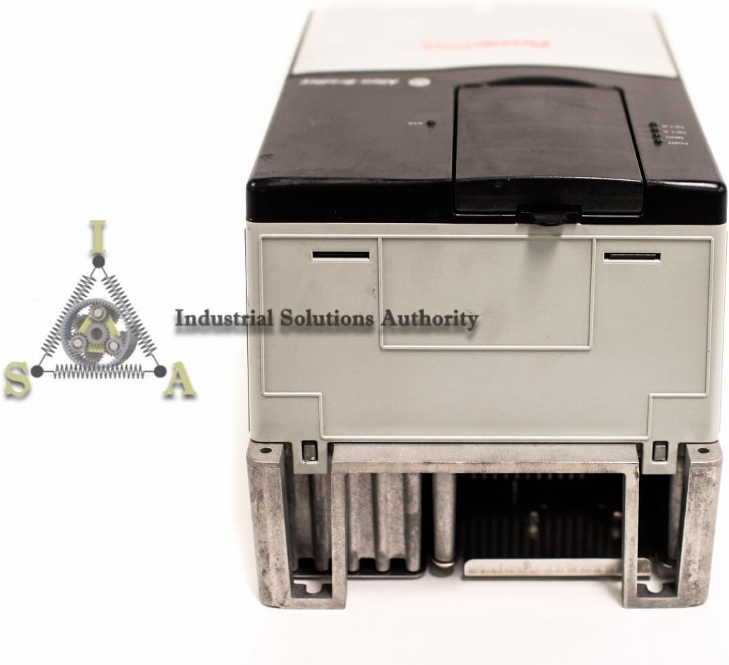
Figur 4: Nederst view of the PowerFlex 70 VFD, showing the base and mounting points, indicating its robust construction.
Spesifikasjoner
Key technical specifications for the Allen-Bradley PowerFlex 70 VFD, model 20AC015A0AYNANNN:
- Modellnummer: 20AC015A0AYNANNN
- Produsent: Allen-Bradley
- Effektvurdering: 7.5 kW
- Inngang Voltage: 400V AC
- Produktdimensjoner: 16 x 16 x 16 tommer (omtrentlig)
- ASIN: B01FKCM8CU
- Dato først tilgjengelig: 12. mai 2016
Garanti og støtte
For warranty information, please refer to the documentation provided at the time of purchase or contact your authorized Allen-Bradley distributor. Technical support can be obtained through official Allen-Bradley channels or your product supplier.
For additional resources, including detailed programming manuals and software, visit the official Rockwell Automation webnettstedet (parent company of Allen-Bradley).