1. Introduksjon
This manual provides essential instructions for the safe and effective use of your DT321B Digital Multimeter. This portable device is designed for measuring AC/DC voltage, DC current, resistance, and includes features for diode testing, continuity, battery testing, and transistor (hFE) measurements. Please read this manual thoroughly before operation and retain it for future reference.
2. Sikkerhetsinformasjon
Følg alltid grunnleggende sikkerhetsregler når du bruker dette multimeteret for å redusere risikoen for brann, elektrisk støt eller personskade.
- Ikke bruk voltage eller strøm som overstiger de maksimalt angitte grensene for multimeteret.
- Sørg for at testledningene er i god stand og riktig tilkoblet før du foretar noen målinger.
- Bruk aldri multimeteret hvis det ser ut til å være skadet, eller hvis testledningene er skadet.
- Vær forsiktig når du arbeider med volumtagover 30 V AC RMS, 42 V peak eller 60 V DC. Disse volumenetagdet utgjør en sjokkfare.
- Koble alltid fra strømmen til kretsen som testes før du måler motstand eller kontinuitet.
- Ikke bruk multimeteret i eksplosive atmosfærer.
- Skift batteriene når indikatoren for lavt batteri vises for å sikre nøyaktige avlesninger.
3. Produktet er overview
The DT321B Digital Multimeter features a clear LCD display and a rotary switch for selecting various measurement functions. Input jacks are provided for connecting test leads.

Figur 3.1: Foran view of the DT321B Digital Multimeter with key components labeled. The display shows numerical readings, the hold button freezes the current reading, and the rotary switch selects measurement functions. The '10A' jack is for high current measurements, 'COM' is the common ground, and 'VΩmA' is for voltage, motstand og lavstrømmålinger.
The multimeter includes a blue backlight for improved visibility in low-light conditions and a data hold function to freeze the displayed reading.
4. Oppsett
4.1 Installasjon av batteri
The DT321B Digital Multimeter requires two 1.5V batteries (Type 7, typically AAA) for operation. To install or replace batteries:
- Sørg for at multimeteret er slått AV.
- Finn batteridekselet på baksiden av enheten.
- Skru ut festeskruen(e) og fjern dekselet.
- Insert the two 1.5V batteries, observing the correct polarity (+ and -) as indicated inside the compartment.
- Sett på batteridekselet og fest det med skruen(e).
5. Bruksanvisning
Before making any measurements, ensure the test leads are securely plugged into the correct input jacks.

Figure 5.1: The DT321B Multimeter with test probes connected. The black probe is connected to the 'COM' (common) jack, and the red probe is connected to the 'VΩmA' jack for most voltage, motstand og lavstrømmålinger.
5.1 Måling av DC Voltage (V–)
- Sett den røde testledningen inn i 'VΩmA'-kontakten og den svarte testledningen inn i 'COM'-kontakten.
- Sett dreiebryteren til ønsket DC-volumtage (V–) range (e.g., 200m, 2, 20, 200, 1000V). If the voltagHvis e er ukjent, start med det høyeste området og arbeid deg nedover.
- Koble testprobene til komponenten eller kretsen som skal måles.
- Les voltage-verdien på LCD-skjermen.
5.2 Måling av AC Voltage (V∼)
- Sett den røde testledningen inn i 'VΩmA'-kontakten og den svarte testledningen inn i 'COM'-kontakten.
- Sett dreiebryteren til ønsket AC-volumtage (V∼) range (e.g., 200, 750V).
- Koble testprobene til komponenten eller kretsen som skal måles.
- Les voltage-verdien på LCD-skjermen.
5.3 Measuring DC Current (A–)
FORSIKTIGHET: To avoid damage to the multimeter or the circuit, never connect the test leads in parallel across a voltage source when measuring current. Always connect in series.
- For currents up to 200mA, insert the red test lead into the 'VΩmA' jack. For currents up to 10A, insert the red test lead into the '10A MAX' jack. The black test lead always goes into the 'COM' jack.
- Set the rotary switch to the desired DC Current (A–) range (e.g., 200u, 2m, 20m, 200m, 10A).
- Open the circuit where current is to be measured and connect the multimeter in series with the circuit.
- Les gjeldende verdi på LCD-skjermen.
5.4 Measuring Resistance (Ω)
FORSIKTIGHET: Ensure the circuit under test is completely de-energized before measuring resistance.
- Sett den røde testledningen inn i 'VΩmA'-kontakten og den svarte testledningen inn i 'COM'-kontakten.
- Set the rotary switch to the desired Resistance (Ω) range (e.g., 200, 2k, 20k, 200k, 2M).
- Koble testprobene over komponenten som skal måles.
- Les av motstandsverdien på LCD-skjermen.
5.5 Diodetest
- Sett den røde testledningen inn i 'VΩmA'-kontakten og den svarte testledningen inn i 'COM'-kontakten.
- Set the rotary switch to the diode symbol (→|).
- Koble den røde proben til anoden og den svarte proben til katoden på dioden. Displayet vil vise forovervolumet.tage slipp.
- Reverse the probes. The display should show 'OL' (open loop) for a good diode.
5.6 Kontinuitetstest
- Sett den røde testledningen inn i 'VΩmA'-kontakten og den svarte testledningen inn i 'COM'-kontakten.
- Set the rotary switch to the continuity symbol (♫).
- Connect the test probes across the circuit or component. If continuity exists (resistance below a certain threshold), the buzzer will sound.
5.7 Battery Testing (1.5V / 9V)
- Sett den røde testledningen inn i 'VΩmA'-kontakten og den svarte testledningen inn i 'COM'-kontakten.
- Set the rotary switch to the '1.5V BATT' or '9V BATT' position.
- Koble den røde proben til den positive polen og den svarte proben til den negative polen på batteriet.
- Les batterivoltage på displayet.
5.8 Transistortest (hFE)
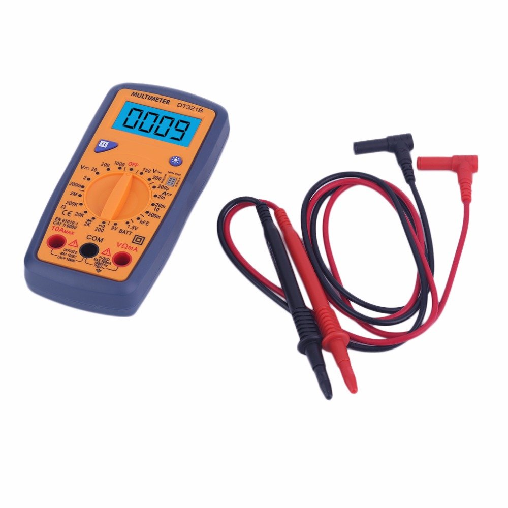
Figure 5.2: The DT321B Multimeter in use, with an inset showing a transistor being tested. The multimeter can measure the hFE (current gain) of NPN and PNP transistors.
- Sett dreiebryteren til «hFE»-posisjonen.
- Identify the NPN or PNP type of the transistor.
- Insert the transistor leads (Emitter, Base, Collector) into the corresponding sockets in the 'hFE' test socket on the multimeter.
- Les hFE-verdien på LCD-skjermen.
5.9 Dataholdingsfunksjon
Press the 'Hold' button to freeze the current reading on the display. Press it again to release the hold function and resume live readings.
5.10 Bakgrunnsbelysningsfunksjon
The multimeter features a blue backlight. Press the backlight button (often integrated with the 'Hold' button or a separate button with a light symbol) to turn the backlight on or off for improved visibility.
6. Vedlikehold
6.1 Rengjøring
Tørk av saken med annonseamp cloth and a mild detergent. Do not use abrasives or solvents. Ensure the multimeter is completely dry before use.
6.2 Batteribytte
When the low battery symbol appears on the display, replace the batteries as described in Section 4.1. Remove batteries if the multimeter is not used for extended periods to prevent leakage.
7. Feilsøking
- Ingen skjerm eller svak skjerm: Sjekk batteriinstallasjonen og lad den. Skift batterier om nødvendig.
- Feil avlesninger: Ensure the rotary switch is set to the correct function and range. Check test lead connections. Verify the circuit under test is properly prepared (e.g., de-energized for resistance).
- 'OL' (Overbelastning) vises: The measured value exceeds the selected range. Switch to a higher range or check for an open circuit.
- No continuity buzzer: Ensure the multimeter is in continuity mode and the circuit is closed.
8. Spesifikasjoner
| Mål | Spekter | Nøyaktighet |
|---|---|---|
| DC Voltage | 200mV, 2V, 20V, 200V, 1000V | ±0.5 % |
| AC Voltage | 200V, 750V | ±1.0 % |
| DC strøm | 200uA, 2mA, 20mA, 200mA, 10A | ±1.8 % |
| Motstand | 200Ω, 2kΩ, 20kΩ, 200kΩ, 2MΩ | ±1.0 % |
Generelle spesifikasjoner:
- LCD-skjermstørrelse: 45x23mm
- Produktstørrelse: 160x76x32mm
- Strømforsyning: 2 x 1.5V batteries (Type 7 / AAA)
- Lav Voltage Symbolvisning: Ja
- Overbelastningsbeskyttelse: Ja
- Diode Detection: Ja
- On-off Detection & Buzzer: Ja
- Batterikapasitetsdeteksjon: 1.5V / 9V
- Transistor Detection (hFE): Ja
- Oppbevaring av data: Ja
- Skjerm med bakgrunnsbelysning: Ja
9. Garanti og støtte
Specific warranty and support information for the DT321B Digital Multimeter is not available in the provided product details. Please refer to the retailer or manufacturer's website for any applicable warranty terms or customer support contacts.