Docooler XUH6362338938855GM
Docooler JINGSHA X99-8D3 Motherboard User Manual
Model: XUH6362338938855GM
1. Introduksjon og overview
The Docooler JINGSHA X99-8D3 is a high-performance ATX gaming motherboard designed for LGA2011 V3 processors. It features four-channel DDR3 memory support, an M.2 NVME slot for high-speed storage, and multiple PCI-E expansion slots, making it suitable for demanding computing tasks and gaming setups. This manual will guide you through the installation, configuration, and maintenance of your motherboard.
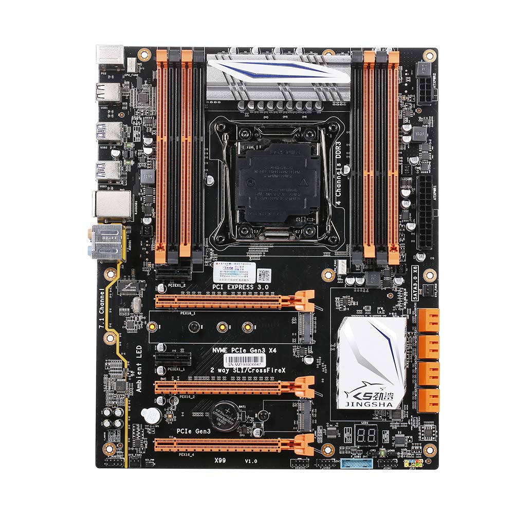
Figur 1.1: Ovenfra og ned view of the Docooler JINGSHA X99-8D3 Motherboard, showcasing its layout with CPU socket, RAM slots, and various expansion slots.
2. Nøkkelfunksjoner
- M.2 NVME Support: Equipped with an M.2 hard disk port, supporting high-speed PCI-E NVME X4 for optimal operating system and application driver performance.
- Quad-Channel DDR3 Memory: Features 8 DDR3 memory slots across 4 channels, significantly improving capacity and performance, supporting up to 256GB.
- Digital Diagnostic Card: Integrated digital diagnostic card automatically tests hardware devices to ensure proper operation and assist in troubleshooting.
- Multiple PCI-E Expansion Slots: Provides 3 PCI-E expanded slots, configurable as X16/X8 to handle various workloads and multi-GPU setups.
- Slitesterk konstruksjon: Built with a 10-layer PCB and high-quality capacitors for enhanced stability and heat resistance.

Figure 2.1: Diagram illustrating the six core technologies and features of the motherboard, including 4-channel DDR3*8, M.2 hard disk interface, digital diagnostic card, 7.1 channel audio, SATA3.0*8 interface, and Crossfire support.
3. Pakkens innhold
Vennligst sjekk at alle varene som er oppført nedenfor er til stede i pakken din:
- 1x Docooler JINGSHA X99-8D3 Motherboard
- 1x SATA-kabel
- 1x I/O Baffle (Backplate)
- 1x CPU Fan Board
- A bag of screws
4. Spesifikasjoner
| Trekk | Spesifikasjon |
|---|---|
| Modell | X99-8D3 |
| Formfaktor | ATX |
| Graphic Slot | PCIE3.0 16X*3 |
| Nettverkskort | Gigabit nettverkskort |
| Lydkanal | 7.1 kanal |
| CPU Type Support | LGA2011 V3 (2629V3/2649V3/2669V3/2678V3/2696V3/2676V3/2673V3) |
| PCB-lag | 10 lag |
| Memory slot | DDR3*8 |
| Maksimal minnekapasitet | 256 GB |
| SATA-grensesnitt | SATA3.0*8, M.2 NVME |
| PS/2-grensesnitt | Mus / tastatur |
| Strømforsyning | 8 PIN*1, 24 PIN*1 |
| USB-grensesnitt | USB3.0*6, USB2.0*6 |
| Utvidet grensesnitt | PCIE 1X*2, M.2 WIFI*1 |
| Varestørrelse | 30.2 x 24.4 cm (11.89 x 9.61 tommer) |
| Varevekt | 930.5 g (32.82 oz) |

Figur 4.1: Detaljert view of the motherboard's rear I/O panel, showing PS/2 ports, USB 2.0, USB 3.0, Gigabit Network Port, and 7.1 Audio Ports.
5. Oppsett og installasjon
Før du starter installasjonen, må du sørge for at systemet er slått av og koblet fra stikkontakten. Hold hovedkortet i kantene for å unngå statisk elektrisitet.
5.1 Installere CPU
- Locate the LGA2011 V3 CPU socket on the motherboard.
- Gently push down the CPU retention lever and swing it open.
- Align the triangular mark on your CPU with the corresponding mark on the socket. Carefully place the CPU into the socket without forcing it.
- Lukk låsespaken for å feste CPU-en.
- Påfør et tynt, jevnt lag med termisk pasta på toppen av CPU-en.
- Install the CPU cooler according to its manufacturer's instructions, ensuring proper contact and pressure.

Figur 5.1: Nærbilde view of the LGA2011 V3 CPU socket on the motherboard, ready for CPU installation.
5.2 Installing RAM Modules
- Åpne klipsene i begge ender av DDR3-minnesporene.
- Align the notch on the RAM module with the key in the memory slot.
- Press down firmly on both ends of the RAM module until the clips snap into place, securing the module.
- For optimal performance, install RAM modules in matching pairs across the four channels as indicated in the motherboard manual or silkscreen.

Figur 5.2: View of the eight DDR3 RAM slots on the motherboard, showing their arrangement for quad-channel memory configuration.
5.3 Installing Storage Devices (M.2 NVME & SATA)
- M.2 NVME SSD: Locate the M.2 slot. Insert the M.2 SSD at an angle into the slot, then gently push it down and secure it with the provided screw.
- SATA-disker: Connect your SATA SSDs or HDDs to the SATA 3.0 ports using SATA data cables. Ensure the power supply SATA power connectors are also attached to the drives.

Figure 5.3: Close-up of the M.2 interface on the motherboard, highlighting its position and the PCI-E Gen3 X4 connection for high-speed data transfer.
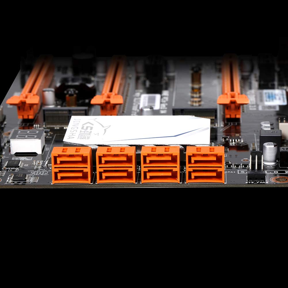
Figur 5.4: View of the eight orange SATA 3.0 ports on the motherboard, providing ample connectivity for storage devices.
5.4 Koble til strømforsyning
- Connect the 24-pin ATX power connector from your power supply unit (PSU) to the corresponding port on the motherboard.
- Connect the 8-pin CPU power connector (EPS12V) from your PSU to the 8-pin port near the CPU socket.
5.5 Installing Expansion Cards (PCIe)
- Locate the desired PCI-E 3.0 x16 or x1 slots.
- Fjern dekselet til det tilhørende utvidelsessporet fra PC-kabinettet.
- Align the expansion card with the slot and press down firmly until it is fully seated. Secure the card with a screw to the case.

Figur 5.5: Vinklet view of the motherboard, highlighting the three PCI Express 3.0 x16 slots and the smaller PCIe x1 slots, ready for graphics cards and other expansion cards.
6. Bruk av hovedkortet
6.1 Første oppstart og BIOS-oppsett
- Etter at du har satt sammen alle komponentene, kobler du til skjermen, tastaturet og musen.
- Power on your system. During the initial boot sequence, repeatedly press the DEL or F2 key (common for JINGSHA motherboards) to enter the BIOS/UEFI setup utility.
- I BIOS må du kontrollere at alle installerte komponenter (CPU, RAM, lagring) oppdages riktig.
- Konfigurer oppstartsrekkefølgen for å prioritere installasjonsmediet til operativsystemet (USB-stasjon eller DVD).
- Lagre endringene og avslutt BIOS. Systemet vil starte på nytt.
6.2 Installasjon av operativsystem
Follow the instructions provided with your operating system (e.g., Windows, Linux) to complete the installation process. Ensure you install all necessary drivers for the motherboard's chipsets, network, audio, and other components from the manufacturer's website or included driver disc.
7. Vedlikehold
Riktig vedlikehold sikrer lang levetid og stabil drift av hovedkortet ditt.
- Støvfjerning: Fjern regelmessig støv fra hovedkortet og komponentene med trykkluft. Sørg for at systemet er slått av og koblet fra strømnettet før rengjøring.
- BIOS-oppdateringer: Periodically check the Docooler or JINGSHA official website for BIOS updates. BIOS updates can improve compatibility, stability, and performance. Follow update instructions carefully to avoid damaging the motherboard.
- Driveroppdateringer: Hold systemdriverne oppdatert for å sikre optimal ytelse og kompatibilitet med ny programvare og maskinvare.
- Miljøforhold: Operate the motherboard in a well-ventilated environment with stable temperature and humidity to prevent overheating and component degradation.
8. Feilsøking
Denne delen tar for seg vanlige problemer du kan støte på.
8.1 Ingen strøm / Ingen oppstart
- Sørg for at 24-pinners ATX- og 8-pinners CPU-strømkontakter er ordentlig koblet til hovedkortet.
- Check if the power supply unit (PSU) is switched on and connected to a working power outlet.
- Verify that the front panel power button cable is correctly connected to the motherboard's header.
8.2 Ingen skjermutgang
- Ensure your graphics card (if dedicated) is properly seated in its PCI-E slot and has all necessary power cables connected.
- Check that your monitor cable is securely connected to the graphics card or motherboard (if integrated graphics are used, though X99 typically requires a dedicated GPU).
- Try reseating your RAM modules. Incorrectly seated RAM is a common cause of no display.
8.3 POST Code Display (Digital Diagnostic Card)
The motherboard is equipped with a digital diagnostic card (POST code display) that shows a two-digit code during boot-up. Refer to the motherboard's detailed technical documentation (often available on the manufacturer's website) for a list of POST codes and their meanings. This can help pinpoint the exact component causing a boot failure.

Figur 8.1: Nærbilde view showing the integrated digital diagnostic card (POST code display) on the motherboard, which assists in identifying hardware issues during boot.
9. Garanti og støtte
For warranty information and technical support, please refer to the documentation provided with your purchase or visit the official Docooler or JINGSHA webnettstedet. Ta vare på kjøpsbeviset for garantikrav.
Ask a question about this manual
Ask about setup, troubleshooting, compatibility, parts, safety, or missing instructions. Manuals+ will review the question and use this page’s manual context to help answer it.